When I’m
looking at various layouts – even great ones – I always look for details that
make a real difference in term of realism and telling a story. Most people will
think about adding a lot of details to bring life, but most of the time, it is in
the “cute” category: trash bins, park benches, oversized traffic signs, cute
fences, people bathing in a nearby creek, etc. While these details aren’t bad
in themselves, they rely heavily on anecdote and hardly tell us how this world
works.
Many people
have mentioned over the time how road vehicles could be the most damaging
liability for a layout. You can fool most people with the wrong trains, but you
won’t a lot of them using cars from another era. Nobody will believe a scene
from the 1990s looks right with 1950s cars in it. Why? Because vehicles are
obvious part of a specific era (size, color, design, etc.). And when adding
vehicles, you can’t start to cherry pick which model you like the most. In this
department, Hedley-Junction is lacking! Most of our cars should be boxy designs
from the mid-70s and to mid-80s. You would mainly find large American sedan and
a few Japanese economic and compact cars. Most of them should be painting in
black colors like tan, metallic gray, light blue, white and black. I recall an era when cars were everything
except garish. Sure, you’ll find one or two muscle cars, but not that much. It
was the post-oil shock era after all.

Well,
talking about vehicle brings me to another subject we started to tackle on the
layout and it is telegraph and power poles. Many people overlook these details.
They are everywhere, but almost insignificant and our brain seems to erase
theme while treating our eyes input! But you really understand how important
they are when you start adding them to a scene.

When we
started to install telegraph poles on our layout, we set a rule. They will
follow the prototype practice in term of design and location. On Murray Bay
Subdivision’s western part, telegraph poles were only used to carry two wires
for grade crossing protection. It means poles were only found on each side of a
given grade crossing and linking relay boxes from the detection system. On the layout,
because of selective compression, it was decided 6 telegraph poles would be
found on each side of a grade crossing on a distance of about 5 feet. This is
the area corresponding roughly to the whistling post. You can quickly see where
I’m going with this. It means each time your locomotive reach the first
telegraph pole, you know you need to whistle… and start the grade crossing
flashing signals.

To make
these telegraph poles, I went the easy way and kitbashed trusty Atlas telegraph
pole. I remove the two upper crossarms and kept the lower one. Only two
insulators were kept. To make the pole more realistic, I added texture by
sliding metal saw teeth on it. This method is highly effective to add realistic
wood texture to plastic. Also, I slightly bent a few poles just like on the
prototype. I hardly remember straight poles as a kid, they were all on the
verge of obvious disrepair.
On the
other hand, on the eastern part of Murray Bay Subdivision, the telegraph line
seems to have been almost continuous. This is probably due to the obvious
isolation of this inaccessible area. This is why, starting from Dominion
Textile up to Clermont, our telegraph line is continuous. Also, a few different
pole designs existed there to conform to the ingrate topography. We did
reproduce that particularity.
The next
step was to add power lines. This is the detail I feel most layouts needs. My
approach to Hedley-Junction evolved and I now think about scenic elements in
such a way if they don’t support the scene, I barely see why I should add them.
I won’t put it if I only find it cute or interesting. It needs to have a
specific purpose. It is true for grade crossing signals, telegraph poles,
street and railway signs, etc.
Last
Saturday, after making the last missing telegraph pole, I started to see if I
could reuse the remaining Atlas crossarms I previously dissected. The answer
was to bash them into electric power poles.
My idea was
to make a realistic tree-phase poles following typical North American practice.
The first scene to be electrified would be Clermont which obviously lacks
scenic details. Each pole
was made from bamboo skewers. Each skewer was tapered to be more realistic. To
do this, I install the skewer on a Dremel tool (just like a lathe), I removed
the excess material with a sanding block. Very easy and it only takes a few
second. Also, it removes the unrealistic bamboo texture from the pole.
After this,
I bashed the crossarms so each of them would be 8 feet long and I only kept two
insulators. They were glued on the skewers and small flat metal wire was used
to make the metal crossarm braces (in fact, we used LED legs that were cut in
the grade crossing project).
A special
pole was made where the power line branch off to connect the propane dealer.
This line runs along the dirt road and ends at the dealer. The last pole of the
line also reflects a typical arrangement with three transformators, meaning the
propane dealer use 3-phase current, which is indeed correct.
Finally, a
pole near the farm house got a single transformator to feed it. These details
are extremely simple, but they tell a lot. I don’t plan to add wire, but when
you see a pole with a transformator, your
brain implies there is a connection nearby.
Planting
the poles was a matter of a few minutes. At first, I installed them at each 12
inches increment, but I found the selective compression didn’t work well. Just
like cars, our eyes really pick up such visual discrepancies, thus I installed
them at 16 inches increment and it definitely looked more realistic. A few
structures were added to the propane dealer to complete the scene and see if everything
works well together. The short answer is yes.
Overall,
the new painted road, the new river bank topography and power lines really give
character to this simple semi-rural scene. Except ground cover, vegetation and
a few signs, I think there is no need to add more. An unexpected result of the
power lines is that they structure the scene and frame it. It tricks your eyes
because, just like in real life, they follow the pole lines instead of
focussing on the background. This is excellent to make you forget the backdrop
is just a plain paper sheet.
In the end,
I consider power lines shouldn’t be considered a fancy detail but one of the
most important one for most layout. They frame scenes, they set the era and
support the story you are telling. Given they can be bashed from readily
available material, cost almost nothing and can be built by any average
modeller, there is no reason to snob these little guys. But be careful to
follow the prototype practices (spacing and dimensions), because you won’t
trick nobody.
For
reference, you can use Google StreetView as a good source for inspiration. Most
of the time, consider poles should stand about 30 feet over the ground.
Crossarm are generally 8 feet long and when multiple crossarms are required,
they are often 4 feet apart. For any special pole, follow prototype pictures.
Using the 8 feet-long crossarm as reference, you’ll be able to figure out most
other dimensions easily.

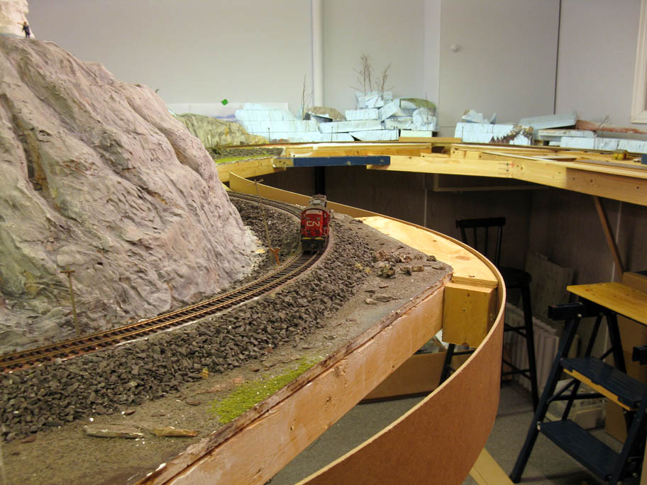
By the way,
we installed the last fascia board and the result is excellent. It’s a shame I
didn’t take a picture of it! Also, I found out even if scenery isn’t done yet,
painting roads with a neutral grey color is an excellent way to bring life to a
scene. Not only is it cheap, quick and easy to do, but it is a terrific way to
validate your design. If the road location is wrong, paint it over and start
again. The more the layout progress, the more I’m convinced using temporary
scenic elements is a good way to figure out complex composition issues, but
also to get the impression the layout is truly progressing. Nobody ever said
plywood and foam was supposed to stay unpainted!