Saturday, February 20, 2016

Intense Traffic on Murray Bay Subdivision

Operating a simplistic layout like ours may sound diminutive. After all, we only have 3 major customers, a small propane dealer and a team track.

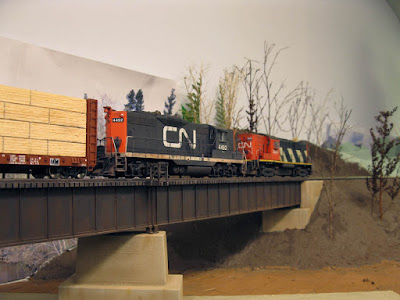
This photo wasn't staged. This is what we got while switching the plant.

However, don't be fooled by this minimalistic approach thinking our trains are small, cute and light.

The RS18s work hard sorting out cars at Villeneuve before leaving for Clermont.


In fact, it's the opposite. Over the last two recent operation sessions following the implementation of our new instructions based on real life train 522-523, no trains was under 20 cars long. In fact, running a 27 cars long train is, as a matter of fact, becoming standard. In term of HO scale on a medium sized basement layout, this is no small feat. And every car on that consist has a true destination and role to play.


Interestingly, Louis-Marie recalled he often saw 20-30 cars long train in his childhood, often pulled by two road switchers. This is exactly was we got without really trying to achieve it.

Who said Clermont was a backwood location? Expect to be busy for at least 1 hour there.
 
Operating the Murray Bay is not about mimicking a dying railway, but about serving a strong customers base. I never thought I would really achieve to make it real, but that was my most enduring ambition since my early days in model railroading, more than 25 years ago.

If I had to give and advice to anybody caught in the never-ending "not large enough layout" plot, I'd say put it at rest and do what you can with what you have. If you follow how prototypes do their job in building, operating and serving customers, you'll be more than pleasure by how realistic the result will be. No, small layouts aren't about heart-wrenching compromises, but rather a pragmatic way to really hit the mark flawlessly.

I'm also pleased to say the scale tracks at Villeneuve is now perfectly operating and adding interest while switching the cement plant.

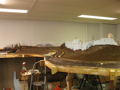
Scenery is progressing steadily and I suspect doing ground cover is a matter of time now. Stay tuned!

Sunday, February 14, 2016

Terraforming Rivière Malbaie Valley

Time to see what lies beyond the bridge isn't it?

Finally, the landform problem is solved. Regular readers know finding a way to blend seamlessly this scene with the rest of the peninsula wasn't a piece of cake. But with the help of styrofoam, floral foam, hot glue and universal mud, nothing is impossible... just be prepared for the huge mess it makes!

 
We thought about reusing parts of already build scenery, but we scrapped everything as it was much more easier to start from scratch. Floral foam was used in heavily forested areas rather than standard styrofoam. It's far easier to plant trees in floral foam, it's made for that.

The cliff was completly remade out of floral foam as it will be heavily forested.


The final result does exceed my expectations by a wide margin. Clermont scene transition with the rock face is now more natura. Also, the tracks now seem to truly curve gently around a riverbed. I'm particularly satisfied with the road in the background.

So let's take a tour of the newly terraformed land...

The farm and road network was built first. Lessons learned while making the landform mockup helped to make it less dramatic and more subdued.

The completed farm scene will more subtle topography.

The tank track is moving over the new propane dealer access road.

A general view from Clermont yard.
Something tells me this is gonna end up in a terible accident... just like Duel!


Then the final result when everything is painted with dark brown latex paint.


The new propane dealer is located on the foreground.


A very nice new railfan spot from the hill.


The next step will be to paint track, but that will have to wait until I get custom made turnouts to finalize the the track road once for all.

By the way, did someone ever wondered found Woodland Scenics' rock mold looked like E.T.'s head? Really weird. I don't believe in coincidence!


Monday, February 8, 2016

Scratchbuilt Grade Crossing Signals - Part 1


I’ve never being a well-organized man. While I can plan a lot, most of the time, I act on the spur of the moment. Last Saturday night, when Louis-Marie asked us what he could do on the layout, I jokingly suggested him to design a dirt cheap way to make working grade crossing signals. I was half serious, knowing he could easily put it off, but I didn’t expect it to be done so quickly and with a high level of craftsmanship.

Grade crossing signals and detection systems are notoriously costly. Add raising shipping cost and exchange rate and it can quickly become ludicrous. Worst, out of 6 signals on our layout, 4 are a special kind you can’t find in HO scale. To make 2 working grade crossings it would cost us at least 500$, maybe more…

Here enters Louis-Marie’s creative mind.  He used an old CD-ROM driver to play a custom made CD with looping grade crossing signal sound.  Jérôme handled the sampling and looped seamlessly the sound file so it could run for 74 minutes. This way, we have a correct sound file for a Canadian crossing. The CD-ROM driver was then wired to a speaker. We still have to find a suitable speaker for this purpose. Our mockup wasn’t loud enough and locomotive sound made it impossible to hear.


The next step was to make a 555 module to control the signals’ flashing red LEDs which only took a few minutes with parts from the junk box.

The real signal at Sous-Bois street crossing in Villeneuve (credit: Unknown)


Meanwhile, I scaled down a picture of the real life signal located at Ciment St-Laurent and started to cut and drill brass tubes from scrapped HO components. Engineering had to be extremely precise to get enough clearance for small wires. It was also required to make sure every brass tube would fit others. I didn’t want to rely solely on solder and decided to make tubes connect in each other. I wired the signal before soldering the parts because it would have been impossible otherwise.


Louis-Marie soldered the brass tubes together and assembled LEDs back to back. The level of precision is quite impressive. He also used shrink tube around the LED to hide their back and make a housing against which the black target will seat.  Speaking of target, we found out Kadee red truck spacers are perfect for 3 mm LED!


Finally, we scratchbuilt a custom ladder made of stiff electrical copper wire. It looks complicated, but in fact, making your own ladders out of wire is a piece of cake. With a Dremel cutoff wheel, I sanded down solder blobs and cut to length the soldered rungs. You are better starting off with longer parts, solder them then adjust the final dimension. It’s easier and it yields better results.


At this point, I added a plastic signal base scavenged from an old HO scale grade crossing signal. Seriously, I always thought HO scale signals were oversized, but they are at least S scale!


Finally, we tested the entire system with lights and sound… and it works flawlessly. Total cost: Nothing and it’s closer to prototype than we could have wanted. I shoot a few very crappy movies to show the result.


Now, you may want to ask me how we will operate the signals. Detectors are a no go. We once tried to design a circuit for each crossing and it wasn’t easy. The problem is each grade crossing has multiple tracks and an uneven number on each side to boot. It would require many detectors and it could be hard to wire everything to work flawlessly. Also, switching operations requires that the signals can be turn off depending circumstances.

Thus, we decided to settle on something more low-budget and simpler to operate. Each grade crossing system will be operated with a regular on-off switch controlling the CD-ROM drive and flashing module. To make sure there’s any delay with the sound file when the flashing system start, the CD will play continuously. In fact, the switch will act as a muting device… idem for the lights.

We are actually discussing the possibility to control the signals with two 3-way switches. Each would be located a few feet away from the crossing were a detection unit should be located. The train operator will turn them on when the locomotive will reach this spot and turn them off when the train clear the crossing. In later days, Murray Bay Subdivision telegraph poles only carried detection signal wires. Thus, on the layout, the switch will be located under the last telegraph pole.

The system is not perfect, but there’s a lot of improvement possible later. Making scale signals is relatively easy and rewarding. The cost is also very low and it was only required to buy some brass tube to make more signals. The first signal, which is also the most intricate, took about 2 hours to build at a leisure pace. Making several signals in an assembly line fashion should be a piece of cake.

By the way, the idea of using CD-ROM drive to handle sound files on the layout will be kept for other ambient sound. This includes industrial sounds near the major factory (Donohue and Ciment St-Laurent) and background sounds like river flowing, ducks and wildlife in the more rural parts of the layout in the same fashion Trevor Marshall do with his Port Rowan S Scale layout.

Sunday, February 7, 2016

More DIY Static Grass Applicator

 
I got the chance to see the new static grass applicator yesterday. It's quite a nice gadget and the results shown in the previous post are excellent when see in real.


To those interested, here are some more close up pictures of the grass applicator. The dimensions are consistent with manufactured versions.


I now got a good reason to continue working on the scenery.

Saturday, February 6, 2016

DIY Static Grass Applicator

It is well-known static grass applicators can cost a lot of money. With our dramatically skrinking modelling budget, it was definitely a no goy. When there's no money, your brain activates: "Necessity is mother of Invention" isn't it?

In fact, I consider building the layout is getting more exciting as the budget shrinks. Everything looks like a real achievement you can be proud of.

In this case, Louis-Marie is pestering me since two years to make real scenery... he means greenery there: trees, grass, bushes, etc. When he learned about grass operator, he was ecstatic but highly surprised such a low-tech gadget could be sold with such an extravagant price tag.


In fact, grass applicators are extremely simplistic machines. The biggest expense was getting a strong enough ion generator which you can get for about 10$ on Ebay including shipping. Other parts are regular electronics you can get from the junk box. Add PVC pipes and reused plastic container with screen and you are in business. Louis says the total cost is about 15$ which is an infinitesimal fraction of the price asked for a brand new Noch grass applicator.

I'd like to give a direct link to an online tutorial, but Louis-Marie followed many and adapted the final design according to parts he had on hands.

To be honest, the ion generator we bough is extremely powereful (read too much) and Louis-Marie had to tame it with bulbs in series.


The first results speak for themselves.  Louis-Marie went also as far as to make multiple covers with different size screen. It is mainly useful if you need to apply grass on a small area.


Once again, a good job done from scratch and that will make a tremendous difference in our approach to scenery.

Tuesday, February 2, 2016

Poor Man's MLW M420 Kitbash - Part 6

Many years ago, when I was in college, I did attempt to scratchbuild my own ZWT trucks for this actual M420 project started 15 years ago.


The result wasn't that back, but making one truck was quite painful since I only had a dull X-Acto blade and very hard plastic sheet to work with. After one truck sideframe, I gave up.

Now, I'm using the very nice Kaslo Shops resin parts for the project. They make life much easier, but without instruction, finding a way to glue them together on Atlas trucks isn't exactly a walk in the park.

On my first try, I followed someone's WIP on Diesel Detailer forum. While well thought, the assembly required altering the copper pickup and solder the wire directly on it. I'm not very fond of soldering and thought there was probably another easier way to glue the sideframes without too much effort. The only thing I kept from his WIP was drilling holes to clear wheel axles.

First try with modified copper pickup.


After looking closely at Efram's M420, I finally got an idea. Keep the pickup as provided by Atlas and modify the resin brake show and spring part. Resin is much more easier to cut to lenght than copper.

One hour later, I had four sideframes perfectly assembled. The spring was cut from the brake assembly and thinned down to fit against Atlas copper tab (connecting the wire). The brake parts were shortened and hollowed in such way I can easily add alignment pins later. Brake shoes were also shortened for the same reason.


Everything was assembled with trusty 5-minutes epoxy after parts were cleaned. Small details like cylinders and air lines will be added later prior to painting. I'm glad I found an easy way to make assemble the sideframes. It means the last big challenge is now behind me. From now on, nothing impede the project.