Monday, October 31, 2022

Stanstead Branch - A 3D Printed Turntable à la Bob Hayden

Small terminals of the late 19th century such as Stanstead Branch and Connors generally used old downgraded locomotives such as 4-4-0. Turntables were thus generally about 60ft long. Several craftsman kits of such turntables are available from several manufacturers, generally from UK, but they cost an arm and a leg. Also, they are generally of foreign design and need to be Americanized.


I wanted something more simple, that could be build leisurely in a few days, around a simplistic mechanism that can't fail. Fortunately, I remembered the old Bob Hayden's article about how he built a branchline turntable using a jack plug as a pivot and bridge girders. That was exactly what I had in mind.

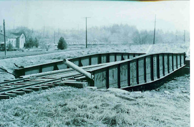
St. Mary's turntable (credit: Dave Tomlinson Collection, trainweb.org)


After looking at several pictures online, I elected to replicate the St. Mary's turntable in Ontario, which I found both suitable and low key to not overwhelm the scene. For the layout, I didn't want the turntable to be the center of attention, but rather a support character. I also remembered that Stanstead turntable was about 65 feet so I made mine that length. It would be suitable for many small and medium steam locomotives and also for small wooden passenger cars. Better plan ahead because you never now what you will do with a layout in the future.

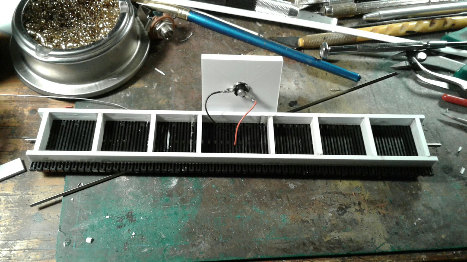
Original styrene frame and jack plug directly soldered to rails


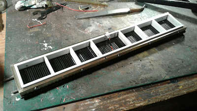
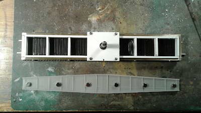
Using a leftover of Central Valley bridge ties strip, I started to build a styrene substructure on which the pivot would be glued. Unfortunately, it was a little bit wobbly and would required much more bracing to counter the torsion. Trevor Marshall suggested to use brass channels and I decided to give it a try. I'm generally not a fan of working with brass, but I decided to overcome my irrational fear. Using 1/8" x 1/4" rectangular tubes (mini HSS), a frame was assembled and soldered in less than a hour. Instead of relying on glue, screws were used to fasten the brass frame to the plastic one, creating an excellent bond between different materials.

Brass frame screwed in place


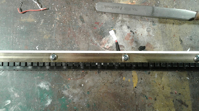
A neat and sturdy assembly. I also add weight, which is good.


The male part of the jack plug was mounted on a 5mm thick laminated styrene square plate. Instead of gluing the plug on the plastic, a tight was drilled so the jack could be screwed  tightly, ensuring a perfect perpendicular mounting. That plate was then drilled and screwed onto the brass frame. This is stronger than glue and if maintenance is required (a solder fails in the future), it can be easily removed. Connectors were also soldered to the wires and plug to add another layer of modularity.

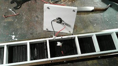
Mechanisms should always be easy to access and maintain


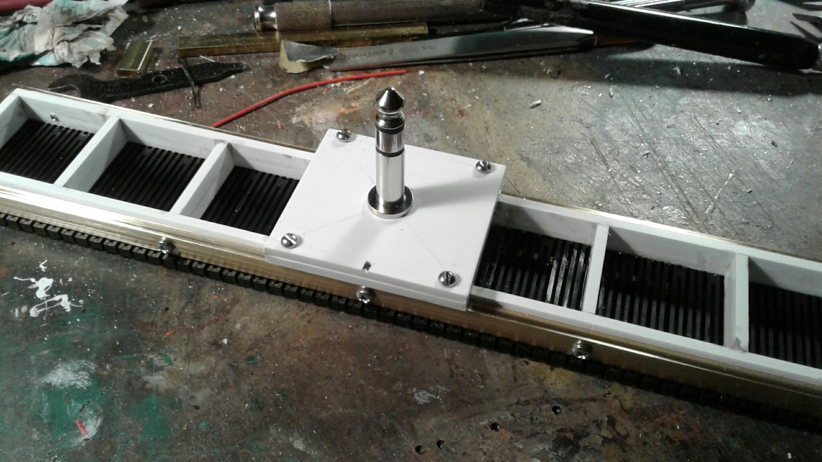
Completed substructure assembly


When came the time to create the girders, I looked at my stash of plastic bridge spare parts. I have a lot of extra girder plates, but they all looked wrong for the purpose. St. Mary's has tapered girders that would be hard to kitbash and building them from scratch would take quite a long time and be costly because of resin rivets required. I fired up my 3D modelling software and designed my own girders to fit the bridge structure. They were quickly printed and assembled.


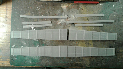
Girders are printed in two halves to fit my printer

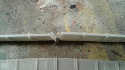
Tongue and groove make alignement easy


The next big challenge was to mount the girders on the turntable. Should I glue them on mounting blocks or think about something more practical. Chris Mears suggested to use neodymium magnets and I gave it a try. It sure worked wonders and I absolutely love the idea it's possible to paint, details and weather independantly the girders from the bridge. Much easier to handle, no need for masking tape and better, you can improve the painting and weathering long after the turntable is installed on the layout. Also, if I ever want to reuse it for a different layout or prototype, just print new girders and voilà.

Six pairs of magnets are sturdy enough for normal use


Magnets are glued on the brass frame and girders


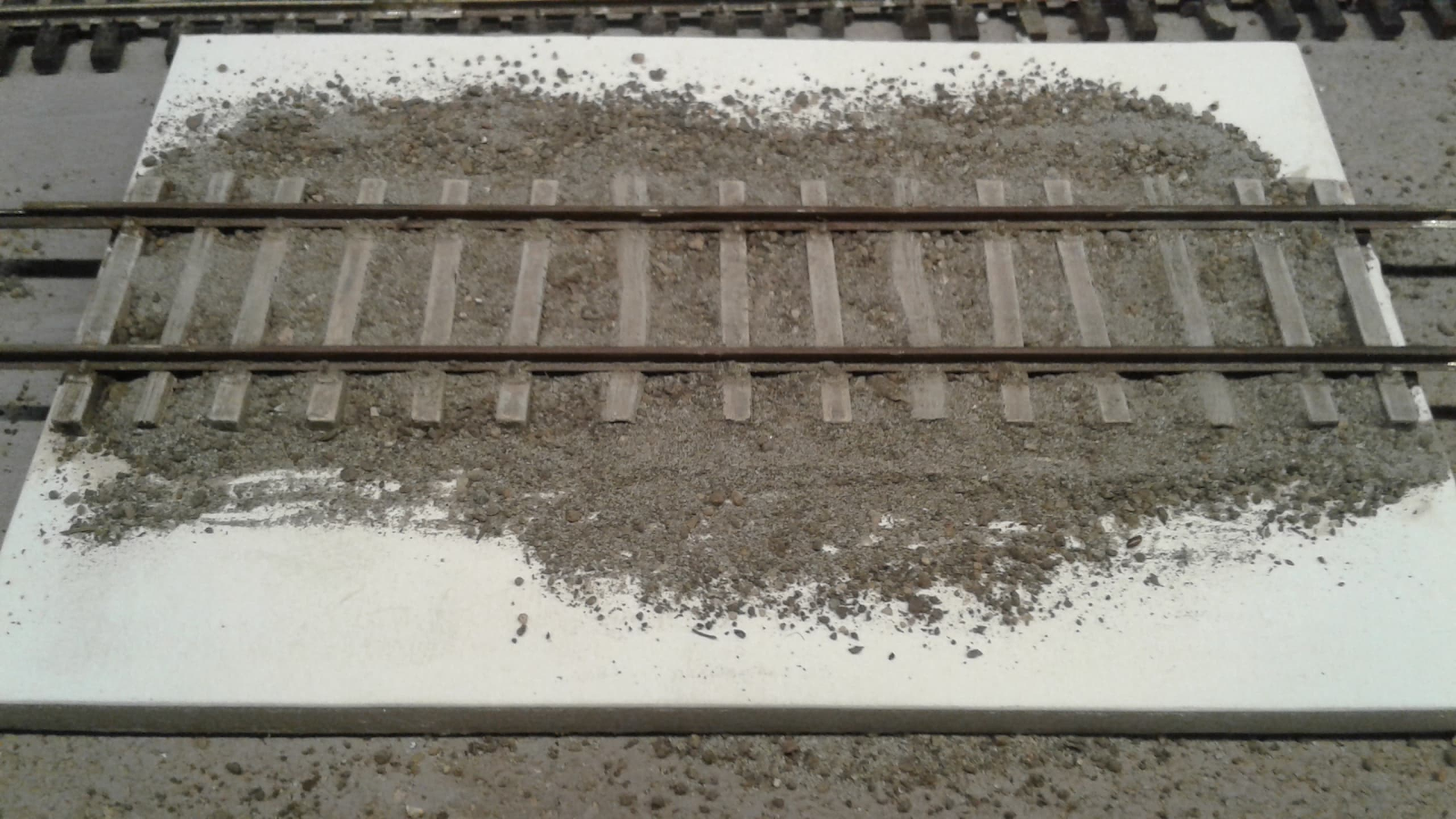
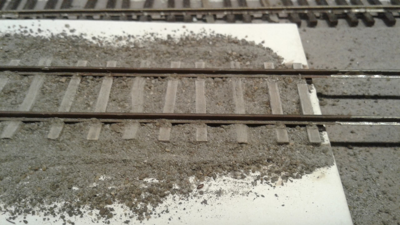
Yesterday, I had fun painting and weathering the turntable. Girders were rusted and received all kind of effects first. Then, I applied two coats of hairspray (chipping medium), a coat of faded black (with bluish hues) and chipped the paint to replicate a structure that was painted maybe two decades earlier and should need a good coat of paint.


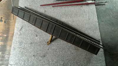
So far, the project is almost completed. I need to cut rails to lenght, add wooden planks on the deck and glue wooden handles so railroaders can turn the turntable. I'm quite pleased. I felt it would be a nightmare and it was not. I can testify Bob Hayden's method is both easy to implement and a sound design. Trevor Marshall suggestion to use brass was indeed the way to go and Chris Mears musing about magnets was another creative way to make a task easier. It was a fun and creative project that was exciting to tackle and see take shape before my eyes.


I can't wait to install the turntable on the layout this week and call it a day! 

Monday, October 24, 2022

Stanstead Branch – Steady Progress

I don’t want to spend too much time on building Stanstead and it’s also a good excuse to unglue me from a screen and do something positive. The first steps of a module are generally quite straight forward when you know what you’re doing. Regarding Stanstead, I want to have it done in a timely manner, before Christmas. It means tracks, wiring, ballast and groundwork should be mostly done by then.


During the weekend, I had the chance to have a lot of free time and the project progressed at an unexpectedly fast pace. Knowing what you are doing help and also knowing how to optimize your time: painting when something is drying elsewhere, etc.


I was able to lay the tracks, including custom distorted ties (about 120 of them), shape the embankments with fiberboard, create landforms out of foam, install a fascia, build control panel (DCC and turntable) and cover everything with a generous coat of mud (Celluclay and latex interior paint). At this point, we can conclude the canvas is now completed and the funny artistic work is beginning.


You will also remark the fascia isn’t straight but rather follow the track geometry. I didn’t like the artificial linear limit created by the rectangular footprint and wanted something more organic and free flowing. I’m really impressed how a simple 2 inches variation can have so much impact on a layout.


I’ve yet to commit to a season for the layout. I’ve been seriously thinking about late summer or late October. Spring could be another good alternative. I’m not sure what I want but I know I’d love to have rich color variations applied in an impressionistic way. It will probably be October for this reason.


The next challenge will be to build the turntable. It will probably be a mix of hard wood, 3D print and a jack plug. It must be both sturdy, simple and efficient.


Finally, I’ve been also working on small projects such as telegraph poles and customizing an Accurail 40ft wooden reefer. Canadian Pacific reefers used to have wooden platform around the ice bunkers. I simply remove the hatches, shaved off the molded grabirons and straps, created new supports and added custom platforms made of styrene. The hatches were glued back in place and new wire grabirons were added. It’s an easy modification and while not 100% accurate, it add a layer of variety to a very generic kit.


Sunday, October 16, 2022

Stanstead Branch - Modelling Turn of Century Track With Commercial Track

You may consider the Stanstead Branch as the spiritual successor to the Connors layout since it is based in the same era, depict a similar end of line terminal and follow the same modelling philosophy of its predecessor.

Modelling 19th century or early 20th century tracks with commercial products may seem to be a daunting task. Regular and rectangular ties spaced closely and evenly hardly capture that whimsical look found on old pictures. As for ballast, any crushed rock stuff won't do the deal since ballast used to be simply dirt collected nearby the railway.

With that said, we must acknowledge my tendency to try to tweak commercial products kicks back facing such a challenge. I'm not a purist regarding handlaid track... it's not my cup of tea though it probably shines the best when dealing with turn of the century stuff. Back then, ties were often barely treated and tie plates were not yet a thing on branches and older lines. In a perfect world, handlaying code 55 would be the winning ticket, but there are other ways to achieve a decent result using Peco American Code 70 track and turnouts.

First, let's take a look at the following picture showing a Boston & Maine yard in Cambridge, Massachusetts somewhere around 1890 and 1900. Tie spacing is quite uneven and seem to follow grossly a 24" spacing (if not more), which was a common practice on branchlines, sidings and yards back in the days.

B&M Boxcar in East Cambridge, MA (source: Historic New England)

Another interesting detail is the tie shapes. Most of them are tree trunks that got the top and bottom squared, but kept their round sides. Remark how many of them aren't regular, but follow the imperfection of the tree. These are roughly rectangular beams, but not squared ones. Also, the tie width varies from very thin to very large. Some have trapezoidal shapes too or twisted ends. How can we model that?


Well, let's start with some Mike Confalone's wisdom who tells us we should always remove one ties out of 5 or 6 from commercial tracks, cut the web and space them unevenly to get a more natural and realistic look. In our case, lots of ties must be removed because we go a step further by replacing some commercial ties by new custom ones made of styrene.

A coat of paint blends commercial and custom ties together


The replacement ties, which I like to call "funky ties" will have all the idiosyncrasies observed in the aforementioned  picture. They are twisted, have rounded edged, sometimes they are tapered and they have large cracks. I start by crudely shaping a bit of styrene, then, using a #11 blade, I shape the sides to give them the curved profile typical of a tree trunk. Finally, several passes of razor saw add wood grain which is further improved by adding cracks with a metal pick and blades.

Yes, this is a tie...


On my first mockup, I replaced a lot of ties with custom ones, but didn't go to crazy with the tie spacing. Also, the funky ties weren't that much funky because I didn't want a parody of a track. However, once ballasted, the custom ties blended so well with the Peco ones it was very hard to tell them apart, nullifying the desire of an imperfect trackwork. However, I really liked how the ballast made of sifted dirt from my yard blended with fine limestone dust replicated well the cheap soil used back in the days.


Having learned from that first experiment, I decided to make a second mockup and go all in with funky ties. The new ones were outrageously distorted and full of cracks. I also spaced the Peco ties further apart to get that 24"-28" look. Also, instead of replacing 1 ties out of 3, I made my life easier by only replacing one out of 5. My thoughts were that having a few very weird ties would make a much stronger impression than many very regular ones. Also, I didn't care that much with tie alignement and some weren't perfectly perpendicular to the rails and it was OK. That time, once ballasted, the ties looked much better and very close to the prototype picture. It seems we have found a winner here.

Ballast blends everything together


Let us summarize the lessons learned:

1) Track spacing is the most important parameter and you can get away without replacing ties if you go forward with this. Remember you will have to separate every ties, which is time consuming and makes laying track harder.

2) Only replace 1 tie out of 4. More than that is useless and less makes it unnoticeable.

3) You custom ties must be very funky. They should be noticeably larger or thinner than the commercial ones. Make them over twisted, tapered and cracked. Don't panic if they look weird and overdone because once painted and ballasted, they will blend with the rest.

4) Paint you ties to look like untreated wood. An easy formula is painting the ties with a tan and white acrylic blend. Don't make it dark, keep it very light. When dry, apply a coat of AK Interactive AK263 Wash For Wood and let it dry. Then, drybrush the ties with off white to make the grain pop up, particularly on custom ties. Once again, don't be shy, the ballast with stain the ties and make then blend perfectly with their surroundings.


Friday, October 14, 2022

Stanstead Branch - A Versatile Small Layout

Digging up old designs of mine is a yearly trend. Recycling baseboards and concepts is normal things as much of us have a few pet subjects we like to gravitate toward. In my case, it’s well known I’ve always been a big fan of rural branchline terminals and 1900s-1920s railways (before and right after nationalization). Connors was cool, but it’s a long stretch of straight tracks, however, another design of mine was inspired by Boston & Maine’s Stanstead station, a small terminal built in 1896 to connect Stanstead, QC to the Massawippi Valley Railway (MVR) that was, at that time, operated by B&M.

This is even more appealing that I've been looking for a neat small design to build a layout for my living room. Something that is both a conversation piece, a playground, a display shelf and an invitation to operate when a friend visit.

Stanstead layout as designed many years ago and never built.


To make a long story short, Stanstead was supposed to be a major rail hub in the mid-1850s, but several political and corporate shenanigans left it out of the game with several railways passing by but none ever serving it. At some point in the 1870s, the MVR built a small industrial spur from Beebe Junction to nearby Rock Island, a small town about 1 mile from Stanstead. However, the larger town was still left alone in its corner, devoid of any direct service. Fortunately, B&M would rectify that 26 years later by providing 3 trains in each direction each day to connect with corresponding trains on the mainline at Beebe Junction according to a June 22th, 1903 public timetable.

Stanstead Branch 1903 timetable (published in Stanstead Journal)


Postcards and pictures of the era show that trains were short. About one combine and a coach, this was more than sufficient. Stanstead was a small location, with only a standard B&M depot, a runaround track, a team track with a freight shed, an enclosed water tank and a small turntable. Not that it needed anything else. I have no idea about the freight traffic that ran over the spur line, but it was probably the usual suspects such as dry goods, lumber, farm equipment, grain and coal. To that should be added granite, which is a specialty of the area. Also, starting in 1896, B&M ran a milk car in conjunction with Canadian Pacific that ran from Stanstead to Lennoxville to Montreal.


A typical passenger train (credit: Matthew D. Cosgro)

As a matter of fact, Stanstead, as I imagine it, is nothing more than the perfect design element you can dream of. It’s the epitome of a rural station without any gimmick. It’s bare bone railroading at its best. For this reason, while it’s based on a prototype, it has universal appeal and I wouldn’t make it absolutely a B&M layout, but rather a generic one that can be used for various railway companies, depending on my mood.


I could easily imagine a converted  IHC 2-6-0 as a starting point

The template being relatively small and the layout self-contained, I had to do some calculations to make sure everything would fit like a puzzle. The basic unit was a train composed of a small steam locomotive (4-4-0, 2-6-0 or 4-6-0) pulling three 40ft freight cars and one combine. It should be possible for the operator to do all the switching moves without using a cassette or any other means. The winning formula was to have a 3-car long track at the end of the line and a 3-car + 1 locomotive long switching lead at the other end. The runaround would be long enough to accommodate 3 cars and a wooden combine.

A mockup to determine the perfect track length

While the plan was easy to determine, making it attractive required something else. Chris Mears often confess his love of sweeping curved tracks on layouts. I agree with him, they are aesthetically interesting and also provide excellent vantage point to railfan a train. With the recent passing of Iain Rice, I looked at a few of his beautiful layout drawings and decided I would add that British touch to the layout by twisting the tracks. Add some topography and it should make it an attractive sight!

A small revision to jazz things up a bit


As for rolling stock and motive power, I already have several small steamers to kitbash and an extensive collection of old time equipment. The nice thing is that many cars in the 1900s-1910s were still very short, including 30-32ft reefers and boxcars, short flatcars and small gondolas. That means that while the layout was designed with 40ft cars in mind, it will look even better with the old rolling stock.

Welcome to Stanstead!


Tuesday, October 11, 2022

Abattoir Legrade as an Inglenook Layout


Hedley-Junction wouldn’t be Hedley-Junction without a good share of recycled and reheated content! On a more serious note, it makes sense to revisit ideas from time to time as new skills, knowledge and experience is acquired.


This time, we revisit an old favourite of mine called Abattoir Legrade which was a meat packing plant located near the actual D’Estimauville Avenue grade crossing in Quebec City. It was served by Quebec Railway Light and Power and CN. I don’t have the exact dates, but it was up and running during the 40s, 50s and 60s. A picture of the modernized plant in the 1960s shows a Canadian National 8-hatch reefer painted in the wet noodle scheme.


Abattoir Legrade in the 1950s

The interesting thing with Abattoir Legrade is the fact it was heavily served by rail given its footprint. They received coal, supplies and cattle by rail and shipped processed meat and animal greases by rail too. In fact, they also trucked a lot of products locally, which meant that both traffic where intertwined.


The building too was a nice little plant painted in white and heavily weathered. The overhanging part over the truck loading bays sported a billboard which was inspired by Disney’s Three Little Pigs. The sidings were surrounded by the plant and the cattle pens, creating an enclosure that was accessible by a gate in a chain-link fence.


In the past, when I tried to model that plant, I tried to be as close as possible to prototype. The results were interesting, but if not implanted on a larger layout, it was a serious waste of space. This time, I tried to make is as small as possible and self-contained (no cassette, no movable part). The footprint was guided by a typical Kallax shelving unit, about 60” by 15”.


First of all, I made some alteration to the prototype by not modelling the main line. It meant that I would need to add a siding to create storage space for switching purposes. At the end of the day, it was now an Inglenook Sidings layout which is a very well-known British switching puzzle (which is more sensible than the Timesaver). While it’s not my intention to use it has an Inglenook, I still thought it would be a good idea to follow its tried and true recipe for track length. All calculations would be based on using 40 feet cars and a GP9… very common rolling stock of the transition era.


60 inches is quite a cramped template and to get a 27 inches switching lead (1 loco + 3 cars), I decided to make it curves toward the backdrop and hide it a tree tunnel. My rationale was that having it disappears in the scenery would give a sense of going somewhere, of a larger world outside… a thing hard to achieve when your track goes straight toward the edge of the layout. One could hide a small switcher (a GE 4-ton, a SW or an S-2 there).

The design also relies on balancing a heavily built right side and a more natural left side. The curved lead also gives an impression of an industrial spur leaving the main line, which enhance the experience.


While the curve radius is quite tight at 15 inches only, it’s enough for the purpose and keep in mind absolutely no coupling or uncoupling happens there. If the footprint is slightly longer, let’s say maybe 2, 4 or even 6 inches more, it’s perfectly possible to make it broader.


Finally, an interesting point to underline is how the fence and grade crossing add a layer of interaction. Protecting the crossing and operating the gate take time and make a session feel longer and more relaxed. One could even add a derail, which would have been perfectly normal at such a location.


At 5 feet long, this layout packs a lot of interesting features without going overboard. It’s based on reality, offers a lot of kitbashing and scratchbuilding opportunities while providing a decent level of operation. Add to that the baseboard and trackage can be built quite fast without thinking about complicated wiring.  Truly an achievable layout in a small and manageable footprint.


CN Woodchip Cars - Now Available for Pre-Order at Kaslo

You wanted prototypical Canadian woodchip cars? Were desperate my project would never see the light (I was!)? Well, rejoice because Kaslo will soon release both cars in resin. I’m extremely delighted to announce CN 878000 and 879000 series will soon be available on the market. From the private messages exchanged with many of your, I’m well aware the demand for these ubiquitous cars is insanely high and rightly so.

For those interested, both are now up for pre-order on Kaslo website.

 HK-28 (CN 878000-878299)

HK-28 kit (credit: Kaslo)

HK029 (CN 879250-879749)

HK-29 kit (credit: Kaslo)


Almost a decade ago – on June 29, 2014 to be precise – I started designing a prototypical CN woodchip gondola lettered with the seldom used CN Rail logo after looking at old railfanning pictures I shot back in 1998 in Clermont, QC. At that time, our layout was being rebuilt into a proper rendition of CN Murray Bay Subdivision and these cars would be required in great numbers to replicate the flavour of the line.


Back then, no manufacturer seemed to feel compelled in producing one of the most iconic Canadian freight cars, one so ubiquitous that any CN layout covering the 1975 to today needs. I even pitched the idea in an email send to a prominent Canadian manufacturer, but it seems from their reply they felt it would garner very little interest from the customers.


After many trials and errors, including revisions done as new accurate data reached me, the cars got more prototypical (thought some details will always stay in the grey zone since I didn’t find the blueprints). For a while, I thought seriously about producing these cars myself under the Ste. Anne’s Car Shop label, but it would be a time consuming and costly endeavour I had very little energy to put into it. I was quite happy to see that John Whitmore at Kaslo was interested in bringing these cars to the general public!


I hope you will like them! It was a long journey that could have been faster, but better late than never! Thanks for your support!