Sunday, March 27, 2022

The Second Empire Cottage - Part 1

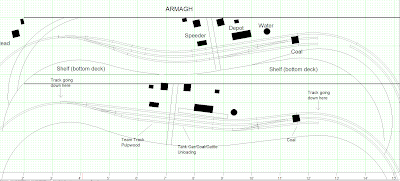
What should be done with the town of Clermont has been a long debate about club members. The number of houses, which type of houses and where to place garages and sheds was over scrutinized more than once. Among things, I recall Jérôme asking me to replicate classic working class houses found in the area.


Maybe one of the most ubiquitous home in French Canadian architecture is the Second Empire style cottage. A staple of Quebec landscapes, with its predecessor the neoclassic cottage which was a modernization of the old and elegant French colonial house, this type of houses were all the craze from the late 1860s to First World War.

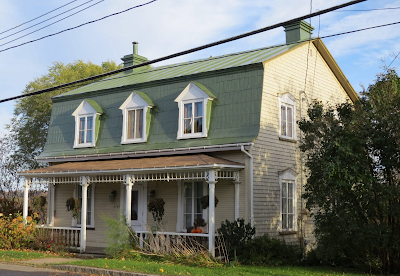
A Second Empire cottage in L'Ange-Gardien, QC


While it also existed elsewhere in Canada and the United States, it probably never achieved such widespread acceptance over a long period of time than in Quebec. The reason was simple, the mansard roof popularized by the Second Empire under Napoléon III was a distinctive French architecture feature which became highly sought after in the late Renaissance. Louis XIV, who wanted a classic architecture that would free itself from the Italian dictates, did a lot to promote this roofline. Even in New France, any person of high ranking or institution would cover its buildings with such roofs. Merchant houses, seminaries, government buildings, hospitals and many others would were all competing in making the most grandiose renditions of this metropolitan style. By the late 17th and early 17th, most cities would feature many buildings of this type and it was easily to understand why. It was both extremely elegant and practical since all the floor space could be used under the roof contrary to the more common sloped roof design.

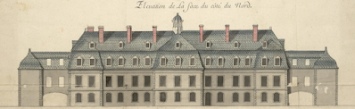
The Intendent Palace, built from 1716 to 1719


However, the big city fires of the 17th century in New France put an end to that type of construction. Seminary of Quebec, after a tragic fire in the early 1700s could no longer afford build a mansard roof and simply elected to rebuild to a simpler and cheaper design. When the Intendant Palace, which gave it's name to Palace Station in downtown Quebec City, burned down too, new bills were implemented. By the 1720s, it has become illegal to build any such roofs in cities where they had been so popular. The reason put forward by military engineer Chaussegros de Léry were quite evident. Mansard roofs used up twice the volume of wood to build and were quite complex to build. At that time, fighting urban fire was all about using firewalls and knocking down roofs to stop the spread of fire. A conventional roof could be dismantled rather quickly but mansard ones couldn't. Worst, once ignited, they would burn for a long time and eject much more embers, making the fire absolutely uncontrollable. From that point on, these roofs started to disappear from the landscape. The few ones surviving until the Conquest of New Franc in 1759 were simply obliterated under the British bombs that destroyed Quebec City daily during that fateful summer.

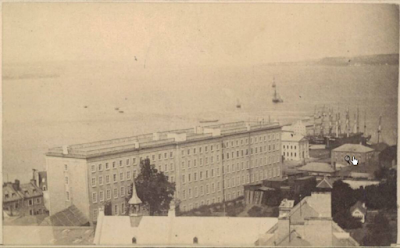
Université Laval's main pavillion, built in 1854 by Charles Baillargé, architect


Significant commercial and cultural exchanges with France only resumed a century later, when La Capricieuse, a French boat, was allowed to anchor in Quebec City harbour in 1855. This event stirred up French Canadian nationalism and culture. Université Laval main pavillion was already under construction at that time, in a neoclassic style reminescent of American practice, including a flat roof with a balustrade which was the first in Canada. Two decades later, when the Second Empire revived the mansard roof style with the new Louvres annex in Paris, the American style on the Université was considered bad taste (and also leaking) and a young architect, Joseph-Ferdinand Peachy, crowned it with a mansard roof and a lantern. It's hard to know if Peachy was aware this would help to give impetus to a visceral architectural trend in French Canada, but it sure did. Associated with the idea of retaking the lost ground by reviving the culture, the Second Empire style was adopted as a way to visually mark the landscape and restore what had been lost for more than a century.

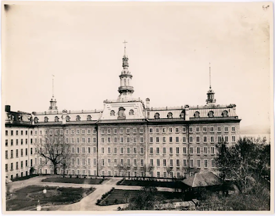
Université Laval and it's new mansard roof (1875)


If one can argue the style was popular everywhere in North America, only in Quebec that sense of cultural restoration was associated with it. Everything got a mansard roof, from convent to working class houses, from chapel to industrialist mansions, from public buildings to factory, even including railway stations, depots, terrace houses and barns. Older buildings would be renovated in the new style and many 16th and 17th farmhouses would get such a roof to gain space and modernize their appearance. It was truly a craze which was officially endorsed by the provincial government who mandated that style for the new Parliament and the Catholic Church which extensively used it for rectories and convent. Nowadays, even as far as Calgary, you can still see these distinctive buildings erected by French Canadians in the Prairies.

The old Convent in Château-Richer is typical of Quebec schools


A particular distinction of the French Canadian Second Empire style was the way roofs were designed. The upper portion would generally be higher, following the old French tradition and the lower part always included a curved part at the bottom which it inherited from the early cottages which used gable roofs which elegantly curved upward. This design was a fusion of the traditional French roof with orientalism of the late 18th century which gained traction in Quebec circa 1780-1790 when governor Frederick Haldimand build an East Asian country house that would be known as Kent House or Manoir Montmorency at Montmorency Falls. This curvature would become a typical trait of Quebec architecture from more than a century. In fact, to the point you know you are out of the French  Canadian  sphere of influence when curved roofs are no longer in sight.

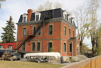
St. Anne Convent in Calgary was built by French priests


That curvature varied from region to region and from builder to builder. Each area, even each village, had its own variation. In My hometown of Château-Richer, mansard roofs lower parts are made of a full circle arc with no straight lines, creating an extremely elegant rooflines, particularly on 4 sided version. In the case of Charlevoix, the lines are less elegant and the lower part if a straight line with a diminutive curved section. This is what I have replicated on my model.

Typical fully curved roof in Château-Richer, QC


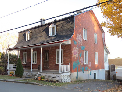
Speaking of the model, I didn't search very far. Up on St. Philippe Street in Clermont, the 6th house from the track is an old working class mansard roofed cottage. The structure is relatively large for the era and location, with a 30' x 34' footprint. Unfortunately, like most 19th century houses in Quebec, it had been poorly renovated in the last few decades, losing most of its appeal. Gone are the trims, the clapboard siding, the diamond tile tin roof, the elegant French style casement windows. Most openings are now a parody of what they were, many condemned and the remaining ones enlarged or reduced to clumsy proportions. Even the dormers have been bastardized and the old brick chimney was replaced by a steel one. That said, the house still has that homey vibe all these old cottages have... with some care, it could be restored to its former glory.

A typical (poorly) modernized cottage in Clermont, QC


However, since the layout is set in the 2000s, I have no reason to replicate a pristine cottage and I made sure it would capture that denatured appearance of today. The first cottage I built for Clermont a few years ago was also a home that was trashed in the 1970s and clad in asbestos shingles. I have to kept up with the theme! That said, the Second Empire cottage, albeit disfigured, is in great shape and very well-maintained. That's something I must keep in mind.

I've reached the point most of the house is done and painted. The incoherent pattern of windows is voluntary, to capture the prototype as close as possible. The presence of a PVC sash window on the rear side show that the casement windows were probably replaced in two different phases. New steel doors patterned after historic models and painted black show the owners probably want their house to still retain an air of grandeur...


My model is relatively straightforward, being an assemblage of styrene sheets covered with self-adhesive roof shingles. Interestingly enough, I had to mix grey and black shingles to finish the job. When it was time to paint them, I found out the real color wasn't black or grey, but rather a dark pink! I gave much better results under interior lighting and softened the harsh black and white contrast nicely.


The next step will be about weathering the siding, scratchbuilding the new chimney and crafting a foundation that will be embedded into the layout scenery. The house will be removable, only sitting on the foundation.

A beautiful 1920s revival style company house, Clermont, QC

Interestingly enough, when Donohue was built, the company constructed several houses for its directors and employees. While "modern", all these houses were built by taken inspiration from the regional and traditional styles. Fortunately, these company houses still survive and most of them are well preserved and maintained.

Friday, March 25, 2022

Completing the Peninsula Scenery

Last Wednesday, it was club layout time and with the road and retaining wall out of my way, it was time to apply some scenery magic to Clermont yard.


This last stretch of scenery was supposed, if I recall correctly, to have been done in the first fall of the pandemic, but for various reasons, it never happened. As always, the groundwork was done using a mix of Celluclay, brown latex house paint and water. It was relatively easy and after about 30 minutes, the road was now firmly embedded in earth and the railway embankment done.

The next step was to ballast the rest of the yard, which was about 16 inches long. I used my usual custom mix of shifted local stones, sand and dirt. However, following several discussions with Chris Mears about ballast, I added some Woodland Scenics Light Gray light ballast? Why? Because we have discovered it was common to see very light stones inclusions in ballast. They are subtle, but hard to replicate with natural stones that are darkened by glue. No need to add much material, just a pinch and it makes a drastic difference, capturing that contaminated ballast look.

Ballast is a rich subject to model...

Speaking of contaminated soil, I also applied some unsanded sand-colored (!) grout to model sand accumulated on the road shoulders. Contrary to real dirt and sand, this mix don't change color when glued, which give a little bit more control. Also, I sprinkle the surface with olive green ground foam. This add relief before applying static grass and replicate these tiny plants starting to grow under the dead grass in May.


The last use of stone was on the embankment and mainly the ditches were several layer of rocks, crushed limestone and Woodland Scenics ballast were glued do to create a drainage ditch. All this will be covered later in grass.

As per my usual recipe, I don't wait for Celluclay to dry, but start applying scenic material on a fresh layer. It acts as a glue and reduce the quantity of white glue to use. I take pinches of yellow static grass and daub it on the surface, leaving patches of dead vegetation. I generally do that near the roadbed were drainage reduce the amount of water in the ground. For the same reason, very little dead grass is found at the bottom of the ditch where water revive the vegetation faster in springtime.


For more color variation and realism, I also used weathered sisal and jute ropes gathered from my garden and cut between 2 and 4mm long. They have much more variation in color than commercial product and their greyish tones are perfect for dead plants.

The next step is the easiest one as I fired up the static grass applicator and cover large swat of land with a custom mix of various mint green, spring green, yellow and burnt grass fibers. I also make sure the mix isn't perfectly blended in the cup, which enhance the random application of colors. Also important, I don't try to cover everything in once pass and one blend. Instead, I covered maybe 1/3 to 1/2 of the surface with random patches of white glue. When the first pass is done, a second one complete the basic layer of grass.


After this first layer, I added greenish tuffs here and there to replicate early spring flowers. They are pressed into the mud and flooded with diluted white glue. Also, at that point, I sprinkle crushed dead leaves here and there... Mainly around the track and at the bottom of the ditch. More gravel is also added there and flooded with glue too.


From that point on, I use cheap hairspray to add adhesive in random places where I want more color variation or density. It's easy and it fixes everything. Don't refrain from building several layers, this is how you achieve realism: color + texture.


The final touch is something only people living in places that receive a lot of snow during winter with understand. To fight against ice and packed snow on roads, a lot of abrasives are used. While salt to lower the freezing temperature of water is well known, the main ingredient is generally sand and very fine crushed stone. As expected, snow plows constantly eject that dirty mix on the road shoulders where it can create a cover of powdery and greyish material over grass. I thought it would be cool to do the same. I sprinkled sifted brown dirt over the static grass on the road shoulder and blew away the excess. I also added some more on the asphalt road, by the curb. Using a large pencil, I brushed that powder to make it stick on the side where vehicle wheels don't run.

At the end of the day, the entire process took less than 3 hours, including cleanup. More than 8 feet of scenery have been done in one pass, at a leisure pace. Small bushes and trees will be added later, but it shows how fast doing mundane scenery is. No excuse to believe it's hard and time consuming. It is not. You probably wasted more time last month programming a decoder or chatting online about trains!


Stone dust for winter 

Thursday, March 24, 2022

Some Love for the Wall

Not everything is doom and gloom at Hedley Junction. Finding our groove is important and we have started again on completing the scenery around the yard.

In light blue is the old roadway

A few weeks ago, Jérôme found out the long sweeping road in Clermont was dangerously warping. It hasn't been glued down and the 8 feet long cardboard piece was behaving in a funky way. I was becoming increasingly obvious we couldn't force the road back where it should be. I suspect this happened because we spliced too long piece of cardboard. Everything from the grade crossing to the splice joint was aligned, but after that point, it was banana territory.


We had two options: redo the entire road, which I wasn't eager to do, or simply cut the warped piece and call it a day. After a short debate, we went with the pragmatic approach... cut the road. It may sound lazy, but it wasn't completely. Indeed, years ago, the original road had the same location and looked great. Also, we felt the longer road wrapping around the peninsula didn't look right. It was prototypical to some extend, but it didn't look great. It felt like the road should be shorter and the peninsula end be pure wilderness to separate each sides. It didn't take long to cut the road and settle the matter once for all!

Some PanPastel didn't make the wall look better...

The next big challenge was the stone retaining wall. As you know, I hand carved it out of a piece of cardboard months ago. Then it was hand painted and colored with pencils. I later added dark pen lines to replicate missing mortar in the joints.

Everything looked flat and homogenous

But at the end of the day, it was still looking like a piece of cardboard. I then tried adding oil washes and pastel chalks, yet it was still cardboard. Frustrated, I decided to go back to Martin Kovac for inspiration. Using plaster of Paris, I filled the scribed lines and sealed the plaster with Dullcote. When dry, I added shadows and highlights using a fine paint brush and diluted acrylic paint. It was much better! It was finally stone.

Irregular plaster mortar joints add relief and make stones stand out

I brought it back to the layout, installed and felt it was fitting perfectly my vision of a poorly maintained stone retaining wall! With theses hurdles out of my way, there was no longer any reason to postpone completing the yard scenery once for all!


Friday, March 18, 2022

DCC Frustrations & Hopes

 In the last few months, the DCC system on Hedley-Junction started to fail... First, it was Rapido's SW1200RS locomotives acting funnily. For some weird reason, when we started using these locomotives, some issues with decoders started to appear. Other locomotives on the layout at the same time started to have serious problems. Motors acted weirdly, producing unhealthy noises, then, we loss control of them. Some would be be running perfectly forward but would run full speed at step 1 on reverse. Worst, for some, you could control the sound but they were idling, unable to move.

Then, I started to run some brand new locomotives from my collection and they would perform fine. A reset was performed on the DCC system and a few locomotives. Finally, all battery from the control cabs were replaced. It kind of worked, but we couldn't salvaged the SW1200RS which are, for the foreseeable future shelf queens until investigation kick off.


It was a really frustrating moment. Coming back from the lockdown, restarting the club meeting and feeling the mechanical aspect of the layout is crumbling apart was disheartening at best. So much efforts to reach that point wasn't fun at all. We are now embarking in a program to reset decoders, readjust each locomotives, clean and lube them. Two years of semi-hiatus wasn't great for the layout.


Also, over the last year, a strange chemical process started to attack the nickel-silver rails. Corrosion similar to rust started to pit the rail surface. Dark brown and black, these spots couldn't be removed by chemicals or polishing. A small test section polished with 320 grit sandpaper removed some spots, but they reappeared quickly. We all know sandpaper is never a solution anyway.


This corrosion creates all kind of issues with the locomotives. It's particularly problematic with sound equipped models. So far, it seems Athearn Genesis geeps are performing the best. I may be warming toward newer Athearn products to be honest. I'm not a fan of the flimsy details, but I have to admit after a two year hiatus, they are still performing brilliantly. However, most other locomotives aren't so lucky.


We've been investigating the rails using a magnifying glass and lots of micro abrasion can be seen. To be frankly honest, in the early days of the layout, our methods were coarse like many beginners and we didn't care enough for our rails. Now, we pay the price. However, the corrosion issue is strange. Temperature and humidity conditions didn't change since the early days of this layout. The spots appears everywhere, but are much more present in Villeneuve yard were a lot of ballast was glued down using powdered resin wood glue. I've wondered if this could have created a chemical reaction, but it doesn't seem to be a likely cause.


At the end of the day, fighting this corrosion is almost a lost battle as the last few months have proven. We do our best to keep track clean, but there is a limit to what we can achieve. As we speak, we have started to equip a few stubborn locomotives with keep alives. This isn't my first choice solution, but it certainly improves greatly performances by making the locomotives run flawlessly.


With these lessons learned, I know I'll take more care with rails on Monk Subdivision. Live and learn, once again!

Saturday, March 12, 2022

Monk Subdivision Staging Yard Conodrum

Monk Subdivision is progressing at a decent pace right now. I’m currently fine tuning the staging yard design and cutting plywood for it. In the recent days, I did a few experiments with tracks that completely changed my approach to what I’m about to do.


The biggest concern about the hidden staging yard is that vertical clearance is minimal. We are talking about 6” at best here which isn’t close to any recommended practice.  The answer is simple, how do you deal with access, derailed equipment and cleaning the tracks? I wish I had more vertical clearance, something close to 10” or 12”, but it isn’t possible. I have no place to spare for a helix and I want to keep my grade under 1.5% at any cost to maintain a good performance for my steam locomotives. With that known, I have to design my way around that hurdle.


The first thing is to make the foreground and background on the upper deck partially movable so I can access the tracks in case of an incident or simply for maintenance. This is even more important where turnouts are located. If possible, I wish to put turnouts where they will be easier to access. On the left, it means I can place a few ones under the hill in the foreground. The hill will be a good excuse to have an access slot in the fascia so we can visually monitor what’s going on in the staging. Other turnouts on the left will be located after the big curve because they will clear the lower cabinets on the wall. I certainly don’t wish to see any complex wiring and controls there. On the right sides, all turnouts are located against the wall and before the curve because this is where access is best at all time.


Another big issue is that my staging yard will need to be built partially on a grade on both sides. It means most of the yard throats will be inclined. I did some tests with Rapido Super Continental coaches (my longest and most capricious cars) and it works fine if the grade is constant and turnouts are far from vertical transitions. We can consider that a done deal.

Revised staging plan

The next issue is derailment. These things are frustrating, but even more when they happen in hidden places. For this reason, a lot of rerailers will be installed on every hidden track to minimize risks. They cost almost nothing and I feel this is a much needed insurance.


Speaking of unreachable areas, I created alcoves in the upper deck to follow the track flowing curvature. This is both for aesthetics and to provide a shelf, but also to make my life easier when handling trains in the yard. I will install a fiddle track that will be built at the bottom of the left alcove. Trains there will be both visible and easy to handle. The spot will be useful to build or break trains there, creating new consists without having to fight under the upper deck elsewhere. I can also serve as a programming track or to stage the local freight train. This is the only train that needs to be frequently changed. This track will be good enough to handle it and I’m planning to install a series of drawers under the layout right there to make staging easier.


Now, the last big issue to take care of... Turnouts are a real paint in the proverbial place. You get short, you lose power, train derails… it’s the main source of problem on a layout. Now, imagine using them under in hidden places! I can already imagine the disaster. My original plan called for the use of old PECO Code 100 Streamline turnouts salvaged from our second club layout. They are almost brand new and in great shape, but I found out they run a little bit rough with modern cars, particularly the Rapido ones that start dancing on the frogs. I also tried with old Blue Box cars and I got the same results. It’s also very noisy. The turnouts are fine, but on a grade, I don’t trust them. I did the experiment again with Peco Code 83 turnouts and the ride was much smoother and quieter. I knew I would have to think twice about using the Code 100 turnouts. Worst, I found out I hadn’t enough of them to build the staging yard, so I had to make a decision.


This decision is simple, I won’t use Peco Code 100 turnouts… and will upgrade my design with Peco Code 83 or Code 70. I prefer more reliable components to be honest. I see the problem at the club layout and don’t want them replicated here. Speaking of turnouts, I’ve come to appreciate Peco’s new unifrog design. I like the idea of being able to upgrade the system later on. The reason is simple, I have many old DC locomotives I want to use and Unifrog give me the chance to make it possible to run both DC and DCC. Also, the Unifrog design comes with continuous solid rail points instead of hinged ones. Much more reliable for electric current and less prone to derailment.


For these reasons, I’ve redesigned the yard to only use Peco #6 Unifrog turnouts. It comes with a price tag, but I know you can’t go cheap with turnouts. Many will comment that at this point, I should invest in Fast Track jigs and build my own turnouts. That would be a great idea, but it comes with a serious caveat; I both suck at mechanical stuff and plainly hate mechanical stuff. I may understand the general principles, but I’m terrible at implementing them. A fifty hours spent at the benchwork to build 25 turnouts  I know will be less than great doesn’t seem appealing to me. Bear in mind I totally respect people building their turnouts. We all know it’s the best way to go, but it’s a red line I’m happy to draw knowing my strengths lies elsewhere.


With that said, I’m happy to report the new staging yard is now fully revised and ready to enter the building stage. It will be quite a challenge since I want to implement servos for turnout control, insulated staging tracks and IR detection for a control board that will let me know what’s happening. In the future, I'd like to program the staging turnouts with an Arduino board to make things more intuitive and simpler. I'm not closing the door to automation either since the layout is rather simple.


Staging capacity

This is the most important criteria at the end of the day... How many trains and cars can be staged at once. Since Monk Subdivision saw a lot of traffic back in the days, I wanted enough tracks to hold them all. While I do intend to model mainly the early 1950s, I'll use the layout to run anything in my collection from the 1960s to the 2010s. For this reason, I'll probably run consists made of 3 to 5 locomotives pulling about 30 cars when I'm in the mood for it. Also, some trains on the subdivision were really long. A good example is the Cabot, a passenger train from the late 1960s which can easily be 16 to 18ft long. It's high on my priority list and I really wanted it to be possible.


Using an employee timetable from the 1950s, I've come to this tentative staging scheme which could hold about 140 freight cars and 22 passenger cars at once:

Staging 1:   242 (230) 38 cars (#700 fast freight)

Staging 2:   188 (176) 31 cars (#700 fast freight)

Staging 3:   206 (194) 34 cars (#400 2-10-2 manifest)

Staging 4:   131 (119) 20 cars (#400 2-10-2 manifest)

Staging 5:   127 (115) 19 cars (Fast passenger)

Staging 6:   120 (108) 20 cars (Fast passenger)

Staging 7:   98   (86)   14 cars (#400 2-8-2 manifest)

Staging 8:   95   (83)   14 cars (#400 2-8-2 manifest)

Staging 9:   72   (60)   10 cars (local passenger)

Staging 10: 72   (60)   10 cars (local passenger)

Friday, March 11, 2022

Hindsight 20/20 Post Mortem

When Hunter Hughson contacted me to present a clinic about my Birtish-American Oil tank car fleet I couldn't help but stress the fact my research was incomplete and amateurish at best. My work was everything but an approximation of the prototype. But he convinced me there was a place for this kind of work at a RPM meet.

My hope was to provide a basic frame of data and a methodology which could be improved as new information is found or completed by much knowledgeable people than I. I must confess I'm not particularly well versed in searching through ORER, car drawings and specialized book.

However, I've quite impressed with the interest this clinic sparked and a few individuals like Mike Schleigh and Jim Little contacted me to provide more data unkown to me. I really want to thanks all of them for their invaluable knowledge as it has put to rest many questions that I felt I couldn't answer.

First, Jim Little was kind enough to provide me with good color pictures of BA tank cars. As I speculated, the green paint was not olive nor dark emerald but a rather standard dark green. Tamiya XF-26 Dark Green seem to be quite close but some experiments will be required to find the "perfect" match if such a thing exist.

Then, Ted Culotta and others suggested I took a look at Southern Car & Foundry STC-built tank car resin kits. While these kits are out of stock, a few can still be found here and there. The most useful ones are the 6k gals. 5 course radial tank car and the 10k gals. tank car.

The clinic hand out available on Hindsight2020 groups.io has been updated to reflect these information.

Tuesday, March 8, 2022

Some Action on Monk Subdivision - Benchwork

The Monk Subdivision layout project is moving forward again after a hiatus due to the recent bout of lockdowns in Quebec being phased out. I didn't work on it for almost two months, if not more, and it was time to revisit the basement to push forward with this project.

To be honest, I'm impatient to run trains and nothing more. And if you don't see fancy words such as operations and prototypes, you are an astute reader. For this project, I simply don't care about that since it isn't the main goal. I think each layout is an opportunity to explore a specific set of ideas. In this case, Hedley-Junction and Harlem Station provide me with plenty of action and plenty of prototype oriented modelling. What they don't provide is running trains. Long ones, passenger ones, ones that are prototypically related to the layout concept.


I think I discussed these ideas in the past, but I really like to railfan trains and it doesn't need a lot. Also, I don't see myself building a complicated layout by my own. I just don't have that level of commitment built in me. I'll work tirelessly on short and involved projects, but don't ask me to debug or wire a 40-something turnouts with a clear schedule to respect. It won't happen.


During the last two months, I've been working on other projects and when I started to look back at my old track plan for Monk, questions and observations were made. The first thing was that several technical issues were raised. Building a long curved bridge near a swing gate and out of staging didn't work at all due to conflict with turnouts in the fiddle yard. Making a turntable to run flawlessly is a long and costly endeavour... for something that is seldom used. I do love them, I'm terrible at electronics and mechanics. Monk yard was small, very, very small... too small. And Armagh was cool, but since it's a flat switching district, each grades of both sides were now at 2.4% which I felt was unrealistic and undesirable. If the goal is to railfan, it makes no sense to have such a steep grade because I know many of my steam locomotives are mediocre or passable puller. A True Line U-2-g (yes, I got the upgraded drive version back in the days for a fraction of the price) won't be happy there. The layout must be universal and generic to fit all my needs.

Some benchwork done...

And the swing gate almost finished.


Waiting before moving forward with the project was a good idea because I read a little bit more about Monk subdivision and came to realize a good realistic layout with a modicum of operation was possible. I learned more details about Armagh being the refueling station between Joffre and Monk. From what I understand, it was an obligatory stop for almost every steam trains running on the subdivision. The coaling tower was also wooden and didn't seem to use a raised track, making it an interest small contraption. Armagh also had a nice team track used for a variety of local customers, including pulpwood, produce and fuel. Add to that the coal traffic to the coaling station and you get a clear idea switching the area is just like operating on a well thought switching layout. For those familiar with Trevor Marshall's old Port Rowan layout, just imagine Armagh is the equivalent if it wasn't a terminus.

Who needs more? (credit: C&O Piney River and Paint Creek Subdivision on FB)


Meanwhile, I was also building a 54" long replica of Rivière du Milieu trestle bridge on the NTR, near La Tuque for Yvan Déry's layout rebuilding effort. Seeing such a huge NTR structure made me recognize it was a perfect classic railfanning spot and that it would be foolish to reduce the NTR Abenakis Viaduct to a cramped space in a corner of the layout. I was convinced that if I were to give the impression of a transcontinental railway, I had no other choice but to build a full scale replicate of that bridge and enshrine it on the layout like a jewel. A few discussions with Chris Mears fully convinced me it was the path to follow.

Sketch exploring the role of scenery in a single track mainline design


At this point, you probably know where I'm going on. I reverted back to the initial layout concept and dropped Monk altogether, making Armagh the central scene. This enabled me to replicate a closer to scale Armagh with a 16 feet long siding to stage meets between long trains. This move freed space for the Abenakis Viaduct right were Armagh used to stand. Since it's a bridge, it would be on slight grade, like the prototype too, helping me to create a continuous and gentle scenic grade from staging to Armagh. The new grade is now about 1.6% which seems totally acceptable in HO scale.

A simple scene that speaks volume about the railway purpose


As for the rest of the layout, it's just plain scenery... many feet of mainlines crossing the territory like a ribbon steel cutting through ingrate topography. The layout is now less crowded and much more geared toward railfanning. Minimal radius on visible parts is about 42", which will make long passenger cars not look too silly (they always do!).

Armagh is simple yet packed with action

Two possible versions, the bottom one being more realistic


It also implement a more coherent narrative in regard to the prototype roots of this layout. Just like the real Monk subdivision, the first part is all about climbing and conquering the Appalachian piedmont by snuggling along the topography to keep a constant and acceptable grade for optimal results... After battling the grade through valleys and hills covered in forest, the train reach finally a resting spot to pause, refuel and assess the rest of its journey. This flat spot represent the human contact point with trains... the place were the ecumene can be understood by human settlement, buildings and fields... Then, our train continues it way toward the Atlantic ocean by finding its way through the Appalachian plateau characterized by relatively low hills, marshes and woods before entering staging once again.

A schematic proof of concept

It gives us a 2/3 ration of scenery VS yard, which seems about right to me to keep things simple and realistic. The number of structures to model is now relatively low, but each of them are really interesting. They can also be replaced by other similar footprint buildings to imply a completely different prototype set in a similar region.

Updated track plan and scenery design


As for staging, I've started from scratch too, now envisioning a simple two ended yard with much longer tracks and a possibility for later automation and additional track. The goal here is to get trains moving soon so the layout has a purpose.

Friday, March 4, 2022

Hindsight 20/20 12.0 - Modelling British-American Tank Cars

 I'm glad to announce I'll be presenting a new clinic documenting my effort at modelling British-American tank cars in HO Scale during Hindsight 20/20 Virtual RPM tomorrow. You can register here.


British-American tank cars draw a lot of attention and can be considered crowd pleasers among  modellers and collectors. They were indeed a classic 1940s-1950s sight and many manufacturers offer more or less "accurate" models that doesn't cut it for most of us.


The subject is vast and two different clinics will be required to delve with some depth into this subject. For this Saturday, I will focus on analyzing the historic B-A fleet, documenting its characteristics and paint scheme evolution. These information will come handy to do a comparative study between the prototypes and the suitable available models.


Hope this will catch your fancy!