Sunday, January 31, 2016

Poor Man's MLW M420 Kitbash - Part 5


Another day of work on my poor man's M420. I was happy to find out this morning I still had a set of old Atlas C424 stanchions that fits the M420. I was contemplating making my own with brass, but honestly, I prefer to reuse unmodified delrin parts for the sake of durability.


While I thought I was ready for the paint shop, I decided to make some more modifications to the pilots, particularly the rear one. M420 had a notch under the coupler's box. C424 don't and have an angular pilot shaped like a wedge (or a diminutive snow plow). I'm aware this model is the most unprototypical M420 out there, but locomotives ends must be as close as possible because it's where our eyes are drawn during operation.


I also painted and glossed the shell. If everything goes as I wish, decalling could be done later this week. Reaching this step is a big incensitive to work hard to reach the goal. That and the wonderful model of a Kaslo shell built and painted by Sean Seale. Once again Efram did a terrific job on the weathering. The nice thing is that the level of weathering match my distant memories of a M420 stalled at Château-Richer's grade crossing back in 1986. As you may know, I'm trying to replicate that specific locomotive etched in my brain. You never forget when the train bug bites for the first time...


Back on the model! While the paint dried, I decided to install my custom wood fuel tanks on Atlas snap-on tank part. It was easy as 1-2-3. Using a Dremel cutoff wheel, I sanded down the wood ends until they matched the Atlas tank. For some reason, my tanks were very long and didn't clear the locomotive trucks. Put that on my less than stellar craftmanship back in high school.


Small Atlas air tanks were saved and glued back on the frame but with a different spacing according to the fuel tank. It must be noted M420 and C424 have different proportions. Back in the days, I used to think differences were mainly in grills locations and stylistic, but I was wrong. It means the fuel tanks of my model are quite short when compared to the real M420. However, one must know many M420 did have shortened fuel tanks. That specific M420 version ran over Murray Bay Subdivision because less fuel meant they were lighter than regular ones which were forbidden according to old timetables.


Finally, I started to prep Kaslo Shop resin ZWT trucks. They are finely molded and easy to clean up. I'm actually working on a prototype to see how to mount them on the locomotive. The easiest and most efficient way is described on Diesel Detailer forum by Éric. He's done a great job in engineering a clever solution to that problem. My first try isn't perfect, but I'm getting a grasp of it and think the next three trucks should be quite easier to make.


Saturday, January 30, 2016

Poor Man's MLW M420 Kitbash - Part 4

Well, this project has sat on my shelves for a while and I'm convinced I can now complete it.

As previously said, bear in mind this project is a total fabrication about a M420. It share the general appearance, but if you start to be picky about details, you'll be greatly unimpressed.


The biggest problem I faced when I bashed my first version was modifying the frame and pilots. At that time, I only used CA glue and it looked like an unsolvable issue. Nowadays, things have changed and I was able to resolve it in less than a morning.


Sure I took shortcuts. I decided to keep the pilots as is and work with Atlas C424 front handrails. But I did venture as far as rebuilt the entire steps from scratch. It was much more easy than I thought. To be honest, the steps are a little bit wider than the real prototype, but don't forget I'm working with a C424 frame and shell. While similar, there's many discrepancies.

 
Finally, a few bits of styrene where used to make large triangular anticlimbers similar to the prototype. In this respect, I must admit working with prototype pictures was a big help since plans published in RMC back in 1974 we different that was I could see.

A Detail West snow plow complete the model which will soon be ready to be painted and lettered. The biggest challenge is now to make new brass handrails but that will be another day and I still can paint the model without them.

Friday, January 29, 2016

Fascia & Real Estate

I often discussed about the idea to enlarge the peninsula in such a way the track radius would be broader for better appearance. It was also hinted the river scenery would get also some more inches.


In the end, changing the radius was a no go as it involved a lot of efforts but very little reward. Worst, it was eating up precious space in the aisles. I don't consider cramping the place with the layout will make it more interesting in the end.


But it doesn't mean we were against improving the area. In fact, while determining the fascia location this week, we decided to bump the river width by 3 inches. It's not a lot, but just enough to make the river scene more realistic. It will also help to frame better pictures.


A good side effect of this decision is the track now looks as a part of a large scenic unit instead of dominating it.

Thursday, January 28, 2016

Shaping Clermont - Part 1

A new project is now underway: shaping Clermont area. No deadline, but lots of experiment and mock up.

With some work, this could be a future signature scene.


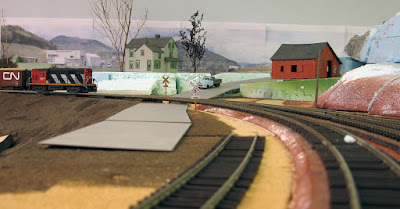
The area was cleaned before starting to work on it. You can still see the ghost remnants of older trackage from when the benchwork was built back in 2010. The two parallel tracks were sidings for a coal industry when the area was still Bassin Louise. The curved roadbed at right was the dreaded reversing loop that took years to get rid of.


The first part started yesterday. I quickly assembled a photobackdrop from pictures I shoot near Wieland back in May 2014. I then printed the backdrop on regular sheet of paper and assembled the mosaic. Nothing fancy, just a mock up to get a feel of the place.


During the evening, I moved the backdrop a few times: left-right and up and down. I documented on picture every single version and while I sifted through my pictures, I found out one of the earliest version was the best. Once again, my late grandmother was right when she used to say the first choice is always right. Doing scenery isn't about precise planning but the harmonious combination of shape.

Helped by Louis-Marie, we found out a few factors were truly important: the location of mountains vs the house, the barn/shed height and the horizon level. When looking at my picture, I also added the terrain profile.

Here's a early version which works best. The interaction between the house, the mountains, the far away plains and the road make for a very open space that seems to stretch over a few miles of terrain.


As we move closer, the four factors start to work together. You can also see how the foam terrain seems to merge with the photo fields near the horizon. In real life, this effect is quite impressive as the scene extend about 3 feets on the barn's right (behind the blue foam ridge).


A part of the debate between me and Louis was to determine if the house was standing on a plateau with a steep border along the track or if it should be standing on a gentle slope running down from the horizon to the roadbed. We settled on a gentle slope thinking the road would look more natural if it wasn't in a deep cut. Here's the first try at shaping the land.


After a while, we thought the house was sitting a little bit too low. Also, the transition between the railway cut near the bridge proved to be challenging. Also, it hides the industries on the backdrop, which were an interesting feature to show we are near an industrial park.


Raising the house didn't help our cause and now the backdrop horizon was almost lost.


Sure, it helped a little bit, making the house appear taller than the far away mountains, but I feel it did more harm than good.


But, I must admit the slope towards the aisle ain't the best way to conceal the joint between the backdrop and the layout. It's why I'm starting to think the original plateau version was better looking.

I think the answer is somewhere between both version. At some point, the backdrop horizon will need to be raised over the foam terrain so we can clearly see the city lurking in the back and the fields at right. The terrain will have to form a somewhat steep rigde that blends naturally with the existing topography. Also, the house should be on a kind of plateau. Nobody would have built a house on such chaotic terrain. Anyway, the backdrop depicts a relatively smooth plain and we should feel it on the layout.

Conclusion?

Still a lot of work to be done and probably the recent mockup will need to be rebuilt almost from scratch. I also cut away the third mountain on the photo (at left) in the process and I feel it was a mistake. I'll probably keep it in the future, trying to blend it with the ridge near the bridge. The reason? Odd numbers always look more natural to the eye. But if it isn't possible, I'll find a way to actually extend the backdrop a little bit to better see the industrial park. Also, the third mountain looks nearer and force the perspective.

The backdrop when the 3rd mountain at left was still there.


There's also a lot of work about the nature of the barn/shed and its exact location. I'm starting to think it shouldn't be a railway-related structure, but comething unrelated. In Wieland, a similar small barn/shed (thought with a gambrel roof) exists near the grade crossing in a similar fashion. That should serve as a starting point in our reflexion.

In the end, while the scene developed in a way I didn't expect, I must admit the 3D effect is beyond my expectation, both on photo and real life. I think we've just built one of the cutest railfanning spot on the layout.

Feel free to share your impression... at this point, nothing is set in stone.

Wednesday, January 27, 2016

"El Cheapo" loads for Bulkhead Flatcars

We recently started to roster a set of bulkhead flatcars, but like any uncovered car, they look silly during operation.


Thus, while the woodchip loads were drying, I decided to make a crude load for fun. It's far to be great, but it will be enough to make us believe the cars are loaded.


I basically started with a piece of 2" x 3" lumber cut to size. Then, I drawn pencil line to represent lumber bundles. Finally, using a ruler and a hobby knife, I scribed horizontal lines to make individual plank.

The new team track really helps to frame the scene.


It will probably never win a modeling contest award, but at least we can move on while I'm still pondering how I'll make realistic loads later. I still can recall seeing unwrapped lumber bundles with huge Donohue's "D" logo back in the late 80s but no picture to work from. So that's another project for the future. I'm in the mood thing should go forward, even if it means going back later. Mockup are great for that.

Tuesday, January 26, 2016

Getting a Grasp of Clermont

The layout try to model an almost mythical train from our childhood: CN #522/523. To make it the real mirror of what we witnessed, we have to both represent what moves it did and which customers it served to have this characteristic look. Coupling various cars doesn't make the cut if they can't tell a coherent story.

To retrace that story, timetables and official paperworks are instrumental in understanding the place, its activities and customers from the railway perspective. Until recently, we didn't have such paperwork and worked from distant memories, hearsay and very rare pictures of that area at that specific time. Most of the time, we couldn't do better than interpolate what seemed to be plausible.


No wonder why until now, the diminutive Clermont yard wasn't up to the task. To be honest, it was always a no man's land hard to define... In fact, back in April 2014, it was this particular side of the peninsula that sparked the whole layout reboot as a prototypical representation of Murray Bay Subdivision. We knew the track plan, but not the specific purpose.

A brand new and never used propane dealer siding near Wieland in 2014.


Imagine when we discovered Clermont's industrial district - while located in a very rural and backwood location - was home to about 7 specific industries and one multipurpose team track. Four customers were all oil or gas dealers including Superior Propane, Texaco and a Petro-Canada subsidiary.

Solugaz Propane's siding and unloading platform. Superior Propane was similar.


From that moment, we were able to understand why we saw regularly "weird" cars lost among long strings of CN 50ft boxcars in the 80s. They were the spices of the railway and now, we know their exact purpose.

With these new facts, it's hard to say we are doing a good job at reproducing Murray Bay Subdivision if we can't incorporate these new defining elements into the layout concept.

The funny thing is this time we aren't finding a location that fits our needs but rather, we recreate a semi-fictious location that support the real train operation. As you already know, it's impossible to model a correct rendition of Clermont, thus we choose to do a protofreelanced combinaison of 3 locations: Clermont yard, Clermont Industrial Park (wye) and Wieland.

Clermont Industrial Park entrance with an old barn in the background.


As crazy as it may sounds, this fantasy place is a closer tribute to Clermont than trying to reproduce clumsily a specific scene (which we failed countless time). In that regard, I remember when Mike Cougill tried to cram too much stuff on his O scale switching layout to fit his vision only to find out the best bet was to keep thing smaller, maybe less prototypical but nearer to the sense of the place.

In that respect, my memories of Clermont are of relatively rundown industrial short sidings along non-descript industries built on Road 138. The most representative place is Wieland, were many moves were actually performed by the crew. There was a passing track, a team track and a small industrial track. It was also the place were MoW cars would be stored and dump cars loaded with rocks and ballast.

Wieland: the left track used to serve many oil dealers back in the 80s and 90s.


Wieland is compact yet full of "industries" without looking crowded: exactly what we need. The fact it is considered almost like a terminus is also a good point. This area feels like you are truly reaching the end of  the line: a goal. This sense of purpose is extremely important because until now, our trains were bound to nowhere and ending in a private property.

Wieland: the team track used to be a busy place.

Now, does all these neat concepts can be translated on the layout? Yes.

The good thing is that many industrial sidings in Clermont are very short, averaging only a few hundred feet (about 36 to 42 inches long in HO). They fit perfectly our tight peninsula geometry.

According to the upgraded track arrangement, we only need to add another siding between the main and the fascia. I know I'm always advocating against adding too much tracks, but when they have real purpose (not merely by fear of lacking operation interest), it's totally acceptable.

Upgraded Clermont


We already made a real life mock up of the new track arrangement and it looks good. Having four parallel tracks really makes Clermont a believeable small yard. The siding near the fascia is the team track. It handles a lot of commodities including lumber, aluminium cables, sand, ballast and many others. The siding on the hill side is dedicated to Superior Propane. The actual space is enough to replicate this industry full size without looking cramped.

Same picture but with a backdrop and more realistic topography
Here's a general view of the mockup area:


It does share a certain ressemblance to the real Clermont yard near Donohue:


We added a speeder shed at the yard's eastern end for fun. It won't be the definite structure, but it makes it clear a building is required to bring a sense of closure to this scene. With the gray and green house on the hill, it enhances depth.


Finally, I consider this last picture as the one that show the true potential of Clermont. While it is a peninsula, the foreground scene blend together with the Malbaie River bridge in the background as if it was one large and deep scene. It reminds me the concept of "Shakkei" or "Borrowed" scenery that Rob Clark discussed in his December 2015 Model Railroad Hobbyist's Imagineering column.


With that last scene complete, I can say we have probably nailed the track plan once for all. I'm looking forward to build this new scene and scenic it accordingly.

Monday, January 25, 2016

Woodchip cars in Action!

It didn't take a long time before Jérôme put the new loaded woodchip cars into motion.


The last operation session at Donohue was a good occasion to see how they looked but also how they made operation less puzzling. Try to figure out when a cars empty and when it's not! OK. We could have used markers but were too lazy.


Making our life easier while switching the woodchip unloading facilities.


Sunday, January 24, 2016

Rise and Fall of a Weighing Station

Have you everdone done something according to the book, with lots of precision, only to find out the entire process was flawed by a single mistake done when starting? It happened to me last Friday.


Before the club session, I drilled holes into the track scales platform to insert the infrared detector per instruction. Boulder Creek Engineering gives you two manuals: one for the infrared detector and another for the weighing station. While both are very well done, the information about the location of the detector on a single track weighing station ain't explained. So I referred to the infrared detector instructions... You'll see later how this was a fateful thing to do...

At the club layout, we tested the weighing station and it worked nice. Boulder Engineering did a very neat job with this little piece of electronic.

Jérôme drilled the benchwork and installed the track scales in place and made a raised platform for the small office.


Louis-Marie worked out the electronics and wiring, but also made the MDF support under the fascia. So far, everything worked fine and it was time to add the infrared detector which was easy as one-two-three.


The result was excellent and then setting the car weight ranges on the station. Jérome carefully documented our cement hoppers maximum loading limit. We were able to get two categories: small slabside hoppers from the 50s and larger modern cylindrical and pressure cement cars.


The final touch was adding a figure of a seated man inside the small office. I'm not a fan of scale figures, but this time, it really bring life to this aquarium. I'll have to shorten the sunshade, repaint the figure and add a chair.


Time to weigh a few cars...


The first car rolled and was weighed accordinglt... then we pulled the second car. Nothing! Just nothing. It was long before we found out the detector was aligned with the cars' knuckles and couldn't detect the gap between the car. Thus, the weighing station considered the whole train as a single car!


What happened? I followed the infrared detector instructions which documented a generic situation when detecting a train take priority over detecting individual cars (exemple: a crossing). We did some test and the best location for a weighing station is outside the rail to get rid of the couplers' interference.

Lesson learned? Don't read carefully the instruction once, but twice.

Now, I'll have to drill new holes and hide the scar I made on the concrete pad! Live and learn isn't it!